
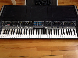
Polymoog model 203A

Polymoog model 203A
I was talking with a friend of mine from Montreal. He runs a synth repair businesses called Atelier Stephan Quendnau. The topic of discussion was the Polymoog, and the sheer audacity of the machine. It's huge, heavy, over-designed, very prone to failure, but completely gorgeous in both looks and sound.
This got me thinking of a Polymoog restoration that I did a few years ago. I decided to pull the information from my archives, and give an overview of the process.
The Polymoog underwent a confusing name change over its production history. The first version in 1975 was a fully programmable polyphonic synthesizer known as the Polymoog Keyboard model 203A. In 1978 a stripped-down preset model was introduced, known as the Polymoog Keyboard model 280A. At that time, the original was re-named the Polymoog Synthesizer.
My client's Polymoog was the original model 203A.
Normally I would check the power supply on any vintage synth before turning it on. However my client had already powered up the Polymoog, so that gave me an opportunity to try it out.
The list of things faulty or flaky was long. Most of the front panel controls didn't work, the output was full of digital sounding hash, and many of the keys didn't do anything.
Before I get into the actual repairs, I should briefly describe the architecture of the Polymoog. Unlike most monosynths which use discreet oscillators, the Polymoog uses a Top Octave Synthesizer (TOS) system. In this scheme, a chip called a Top Octave Generator (TOG), creates a bank of 12 square waves, representing the top octave of the keyboard. Each of these square waves is then passed through a divider chip to create all of the lower octaves. The divider process is similar to a 'suboctave generator' guitar pedal. The square waves may then be processed to create other wave shapes.
In the Polymoog there are two sets of TOS chips, which generates two wave shapes per key (pulse and sawtooth). In effect, there are two oscillators per key. There are also two envelope generators, two VCAs, and two fixed filters for each key. These circuits are combined into a custom chip (called the Polycom), mounted on a small card. There is one Polycom card per key.
The Polymoog is very dense with circuit boards. The first thing you see when you open it up are the main control and modulation board, the mode or preset board, and finally the Moog filter and VCA board. Under that are three more boards that contain all of the Polycom cards.
Here are some photos of the 3 top boards being flipped up. You can see 8 smaller boards mounted on the middle board (2 of them are blue). These are the mode (or preset) boards.
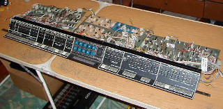
Front Panel Assembly

Front Panel Assembly
The entire front panel assembly and associated circuit boards can be removed as one unit.
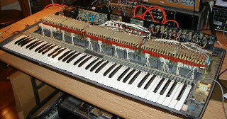
Polycom Cards

Polycom Cards
In this photo you can see the rows of Polycom cards, sitting edgewise along the 3 circuit boards just above the keyboard.
Other than the Polycom chips, there are no custom or hard to find components in the Polymoog. Most of the difficulty in repairing them comes from the complicated design, and multi-board layout. Even tracing simple faults is extremely laborious and time consuming.
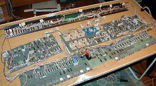
Circuit Boards Interconnects

Circuit Boards Interconnects
One thing that is obvious from these photos is the sheer number of interconnects between boards. Normally, the header pins on the board, and the spring terminals in the cable housing, form a gas-tight connection, which provides a good electrical connection and prohibits corrosion. However, over time these connections loosen, and the contacts corrode.
As I was removing boards, I inspected each of the connectors. Anything that looked corroded or suspect was changed out. Also, the act of disconnecting and reconnecting cables will re-establish the gas-tight connections.
The Polycom cards and mode sub-boards can also be problematic, as the edge connectors can corrode in the same way as the cable interconnects. These are bit more complicated to replace, as you would have to make up a new Polycom or mode board, so I simply removed them all, cleaned the connectors with isopropyl alcohol, and replaced them.
After tending to all of the connectors, I put everything back together, and powered the Polymoog back up. A surprising number of issues had disappeared. The output was still full of digital hash, the front panel controls were still flaky, and some keys still didn't work, but at least I could play it a bit.
I noticed that if I turned off the sawtooth oscillators, most of the noise on the output disappeared. This indicated that there was something wrong with one of the TOS circuits.
There are 2 master oscillators in the Polymoog, one feeding the pulse wave TOS, and one feeding the sawtooth TOS. I probed the output of the sawtooth master oscillator with my oscilloscope. I was expecting a nice high frequency square wave, but all I got an unstable mess.
The master oscillators are classic multivibrator circuits made up of 7400 series logic nand chips, with some transistor buffering. I pulled the old chips out, and replaced them with new sockets and chips. The oscillator was now stable, and most of the noise was gone, but not entirely.
I couldn't immediately tell where the remaining noise was coming from, so I used the highly scientific 'wiggle test'. I wiggled cables, boards, switches, and faders, as I was playing a sustained chord on the keyboard. I found that the noise would come and go when wiggling cables coming from the TOG and divider boards. After checking the Molex connectors, it turned out that the ground pin was not secure.
I believe that this was causing a mix of all of the TOG outputs to bleed into the signal chain. After I replaced the ground spring terminal in the housing, the noise was finally eliminated.
The front panel operation and signal switching inside the Polymoog uses 4000 series CMOS switches extensively. These chips are notorious for getting damaged by static or power voltage spikes. It's quite common for front panel buttons to be non-responsive. Another common behaviour is that latching controls (like the on-off selection of pulse or sawtooth waves), works if you keep the button pressed down. But when you release the button, it doesn't latch.
These chips can sometimes survive carpet-shuffling static zaps and bad power supplies for years, and then suddenly die. It's hard to say how much life might be left before they fail.
The best approach for the Polymoog is to change out all of the front panel CMOS, and replace it with more modern 4000 B-series chips that have input protection. It's a labour intensive process, but the only way to ensure reliability.
As described earlier, each key has it's own pair of dedicated VCAs, envelope generators, and fixed filters on a Polycom chip.
The Polycom chips can fail in a few different ways, but the most common is that the envelope generator does not modulate the VCA, resulting in a dead key. The only way to fix this is to find a replacement chip. Since they have not been manufactured since 1980, the only source is from other broken Polymoogs. Another way around this problem is to move the bad Polycom cards to the extreme end of the keyboard. This simply moves all of the dead keys to one side of the keyboard, but at least they won't be scattered around randomly.
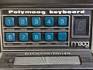
Mode Buttons

Mode Buttons
There are two rows of mode switches on the front panel of the Polymoog, labeled String, Piano, Organ, Harpsichord, Funk, Clav, Vibes, and Brass. Pressing one of these buttons will send preset control voltages to the Polycom cards.
Most people consider these preset patches, but the original intention was to create a family of sound types, not presets. There are two gain controls on the front panel labeled Mode and Direct. By changing the balance between them, and adjusting the other controls on the synth, you can shape the tonality of the synth within the sound family.
It is also possible to press the Var Mode button, lower the Mode gain to zero, and just use the Polymoog like a standard programmable synthesizer.
My client wasn't satisfied with the stock preset Modes. They are all somewhat thin sounding. I modified a few of them by changing the voltage divider resistors on the mode boards. His original request was to recreate the Vox Humana preset on the model 280A. However, that is not exactly possible, as the Vox Humana mode board has an additional filter circuit, and it is missing on the 203A.